- 您现在的位置:买卖IC网 > Sheet目录299 > 71M6543F-IGT/F (Maxim Integrated Products)IC ENERGY METERING
�� �
�
�71M6543F/71M6543G� Data� Sheet�
�Table� 20:� PCON� Register� Bit� Description� (� SFR� 0x87� )�
�Bit�
�PCON[7]�
�Symbol�
�SMOD�
�Function�
�The� SMOD� bit� doubles� the� baud� rate� when� set�
�2.4.6�
�Timers� and� Counters�
�The� 80515� has� two� 16-bit� timer/counter� registers:� Timer� 0� and� Timer� 1.� These� registers� can� be� configured�
�for� counter� or� timer� operations.�
�In� timer� mode,� the� register� is� incremented� every� machine� cycle,� i.e.� it� counts� up� once� for� every� 12� periods� of�
�the� MPU� clock.� In� counter� mode,� the� register� is� incremented� when� the� falling� edge� is� observed� at� the�
�corresponding� input� signal� T0� or� T1� (T0� and� T1� are� the� timer� gating� inputs� derived� from� certain� DIO� pins,� see�
�2.5.10� Digital� I/O� ).� Since� it� takes� 2� machine� cycles� to� recognize� a� 1-to-0� event,� the� maximum� input� count� rate�
�is� 1/2� of� the� clock� frequency� (CKMPU).� There� are� no� restrictions� on� the� duty� cycle,� however� to� ensure� proper�
�recognition� of� the� 0� or� 1� state,� an� input� should� be� stable� for� at� least� 1� machine� cycle.�
�Four� operating� modes� can� be� selected� for� Timer� 0� and� Timer� 1,� as� shown� in� Table� 21� and� Table� 22� .� The�
�TMOD� (� SFR� 0x89� )� register,� shown� in�
�Table� 23,� is� used� to� select� the� appropriate� mode.� The� timer/counter� operation� is� controlled� by� the� TCON�
�(� SFR� 0x88� )� register,� which� is� shown� in� Table� 24� .� Bits� TR1� (� TCON[6]� )� and� TR0� (� TCON[4]� )� in� the� TCON�
�register� start� their� associated� timers� when� set.�
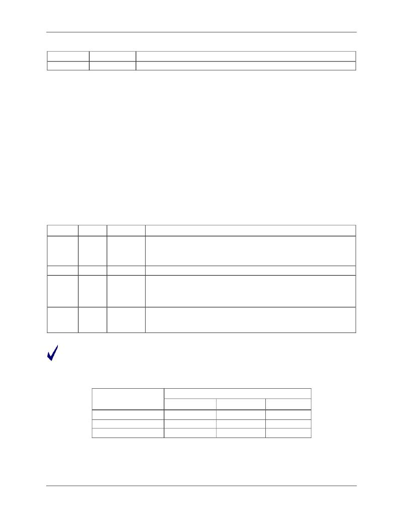
�Table� 21:� Timers/Counters� Mode� Description�
�M1�
�0�
�0�
�1�
�1�
�M0�
�0�
�1�
�0�
�1�
�Mode�
�Mode� 0�
�Mode� 1�
�Mode� 2�
�Mode� 3�
�Function�
�13-bit� Counter/Timer� mode� with� 5� lower� bits� in� the� TL0� or� TL1� (� SFR�
�0x8A� or� SFR� 0x8B� )� register� and� the� remaining� 8� bits� in� the� TH0� or� TH1�
�(� SFR� 0x8C� or� SFR� 0x8D� )� register� (for� Timer� 0� and� Timer� 1,� respectively).�
�The� 3� high� order� bits� of� TL0� and� TL1� are� held� at� zero.�
�16-bit� Counter/Timer� mode.�
�8-bit� auto-reload� Counter/Timer.� The� reload� value� is� kept� in� TH0� or�
�TH1� ,� while� TL0� or� TL1� is� incremented� every� machine� cycle.� When�
�TL(� x)� overflows,� a� value� from� TH(� x)� is� copied� to� TL� (x)� (where� x� is� 0� for�
�counter/timer� 0� or� 1� for� counter/timer� 1.�
�If� Timer� 1� M1� and� M0� bits� are� set� to� 1,� Timer� 1� stops.�
�If� Timer� 0� M1� and� M0� bits� are� set� to� 1,� Timer� 0� acts� as� two� independent�
�8-bit� Timer/Counters.�
�In� Mode� 3,� TL0� is� affected� by� TR0� and� gate� control� bits,� and� sets� the� TF0� flag� on� overflow,� while� TH0�
�is� affected� by� the� TR1� bit,� and� the� TF1� flag� is� set� on� overflow.�
�Table� 22� specifies� the� combinations� of� operation� modes� allowed� for� Timer� 0� and� Timer� 1.�
�Table� 22:� Allowed� Timer/Counter� Mode� Combinations�
�Timer� 1�
�Mode� 0�
�Mode� 1�
�Mode� 2�
�38�
�Timer� 0� -� mode� 0�
�Timer� 0� -� mode� 1�
�Timer� 0� -� mode� 2�
�Yes�
�Yes�
�Not� allowed�
�Yes�
�Yes�
�Not� allowed�
�Yes�
�Yes�
�Yes�
�v2�
�发布紧急采购,3分钟左右您将得到回复。
相关PDF资料
71M6545-IGT/F
IC ENERGY METERING
720-10007-00300
CBL D-SUB 9PIN FMAL-25PIN FML 3M
720-10010-00025
CBL DSUB 9PIN FML-25PIN MAL .25M
720-10020-00300
CBL DSUB 9PIN FML-9PIN MALE 3M
720-10021-00300
CBL DSUB 9PIN FML-9PIN FEMAL 3M
72231-0881
8 POS T/P SHLD 4 GR ASSY
7250B
PANEL KIT BOTTOM FOR R-1220 CASE
731-10061-00200
CBL DSUB HD 15FEMAL-15MALE 2.0M
相关代理商/技术参数
71M6543F-IGTR/F
功能描述:计量片上系统 - SoC Precision Energy Meter IC
RoHS:否 制造商:Maxim Integrated 核心:80515 MPU 处理器系列:71M6511 类型:Metering SoC 最大时钟频率:70 Hz 程序存储器大小:64 KB 数据 RAM 大小:7 KB 接口类型:UART 可编程输入/输出端数量:12 片上 ADC: 安装风格:SMD/SMT 封装 / 箱体:LQFP-64 封装:Reel
71M6543FT-IGT/F
制造商:Maxim Integrated Products 功能描述:ENERGY METER ICS - Rail/Tube
71M6543FT-IGTR/F
制造商:Maxim Integrated Products 功能描述:3-PHASE SOC, 64KB FLASH, PRES TEMP SENSOR - Tape and Reel
71M6543G
制造商:MAXIM 制造商全称:Maxim Integrated Products 功能描述:Selectable Gain of 1 or 8 for One Current Energy Meter ICs Metrology Compensation
71M6543GH
制造商:未知厂家 制造商全称:未知厂家 功能描述:电表IC
71M6543GHT-IGT/F
制造商:Maxim Integrated Products 功能描述:3-PHASE, 128KB, PRES TEMP SENSOR, HI PREC - Bulk
71M6543GHT-IGTR/F
制造商:Maxim Integrated Products 功能描述:3-PHASE, 128KB, PRES TEMP SENSOR, HI PREC - Tape and Reel
71M6543G-IGT/F
功能描述:计量片上系统 - SoC Precision Energy Meter IC RoHS:否 制造商:Maxim Integrated 核心:80515 MPU 处理器系列:71M6511 类型:Metering SoC 最大时钟频率:70 Hz 程序存储器大小:64 KB 数据 RAM 大小:7 KB 接口类型:UART 可编程输入/输出端数量:12 片上 ADC: 安装风格:SMD/SMT 封装 / 箱体:LQFP-64 封装:Reel